Ultimate Guide to Fan Filter Units
23-06-2026
The Ultimate Guide to Fan Filter Units (FFU): Optimizing Cleanroom Airflow, Energy Efficiency, and ISO Compliance
In high-stakes manufacturing environments, the control of airborne particulate matter is directly tied to product safety, operational yield, and regulatory approval. A single microscopic speck of dust, viable bacterial cell, or chemical aerosol can ruin an entire production lot of sterile pharmaceuticals, short-circuit sub-micron paths on a semiconductor wafer, or compromise advanced biological research. To mitigate these risks, industrial cleanrooms rely on continuous, high-volume air changes designed to sweep contaminants out of the critical work zone.
At the center of modern cleanroom airflow design sits the FFU (Fan Filter Unit). Moving away from traditional, massive centralized air handling unit systems that require complex, space-consuming ductwork, contemporary cleanroom design increasingly utilizes localized, decentralized air filtration networks. These self-contained, motorized filtration modules provide precise control over pressure, velocity, and air cleanliness, making them an indispensable component of advanced contamination control infrastructure.
As a premier cleanroom equipment manufacturer, Rayshen Environmental Pvt Ltd designs and builds high-efficiency Fan Filter Unit systems that meet strict international testing standards, including ISO 14644 benchmarks and global GMP compliance frameworks. This technical guide provides an in-depth analysis of FFU technology, operational mechanics, system calculation formulas, and engineering selection criteria, helping facility managers, cleanroom contractors, and HVAC consultants optimize their cleanroom air filtration systems.
What Is an FFU?
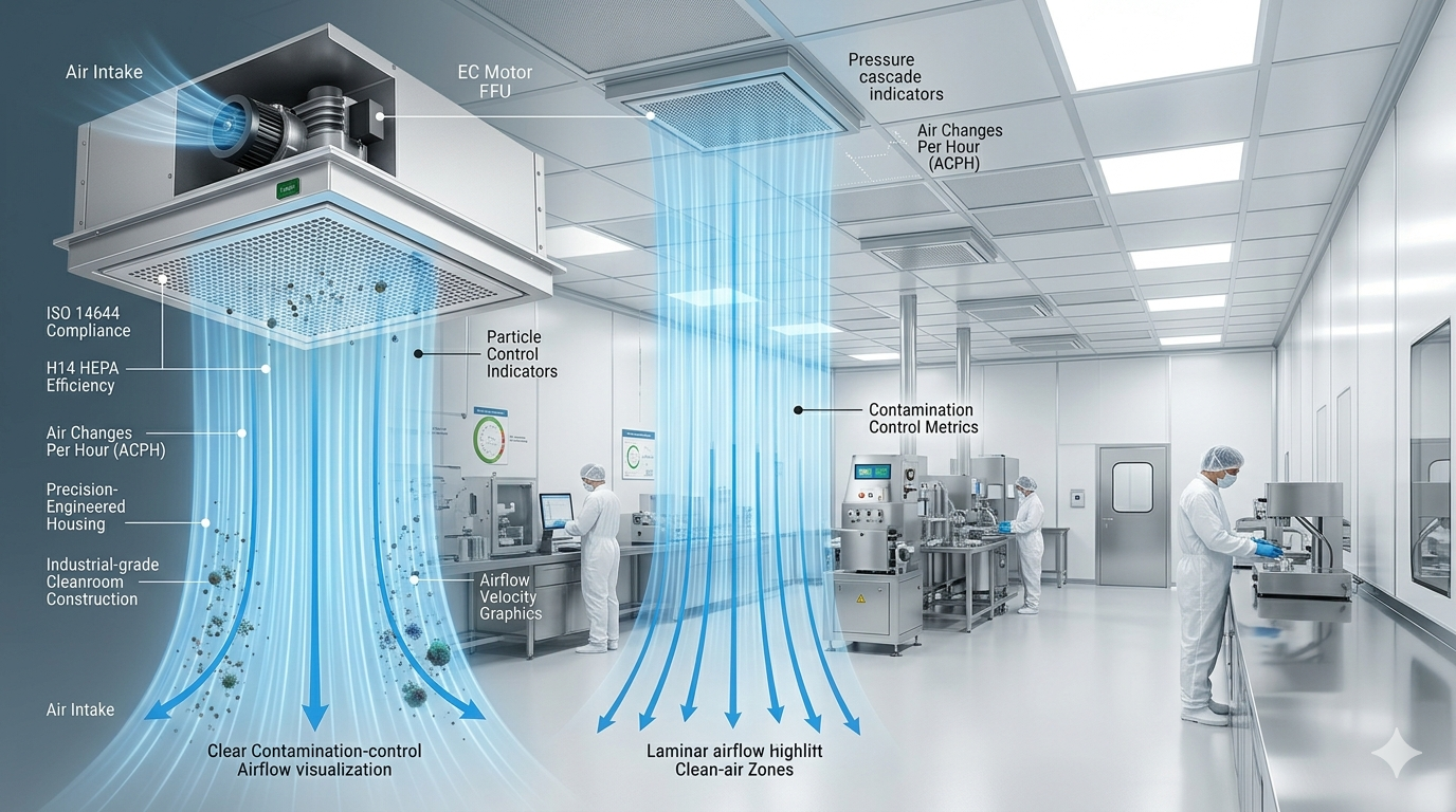
An FFU, or Fan Filter Unit, is a self-contained, motorized air filtration module utilized in cleanrooms and laminar airflow workstations to supply clean, filtered air to a localized environment. Unlike terminal HEPA filter housings that rely entirely on an upstream Air Handling Unit (AHU) to push air through the dense media, an FFU integrates its own internal motorized fan assembly. This built-in fan draws air into the unit from a ceiling plenum or duct connection and forces it through a high-efficiency filter, delivering a uniform, vertical stream of purified air directly into the clean zone below.
A standard industrial cleanroom fan filter unit consists of several critical components integrated into a compact, low-profile housing:
Outer Casing / Housing: Typically constructed from sheet metal, such as Stainless Steel (SS 304 or SS 316), Galvanized Iron (GI), or lightweight Anodized Aluminum, providing structural strength and corrosion resistance.
Pre-Filter Assembly: A primary, low-efficiency pleated panel (typically G4 class under EN 779 / ISO Coarse) designed to trap large dust particles, lint, and debris, protecting the expensive high-efficiency filter downstream from premature loading.
Motorized Fan Deck: Comprises a high-performance backward-curved centrifugal impeller powered by either a conventional Alternating Current (AC) motor or an advanced Electronically Commutated (EC) motor.
High-Efficiency Filter Element: The core component, which is typically a certified H14 HEPA filter or an Ultra-Low Penetration Air (ULPA) filter, responsible for sub-micron particle filtration.
Airflow Equalizer panel: A perforated plate or diffusion matrix located at the discharge face that ensures the exiting air is distributed at a uniform, stable velocity across the entire surface area, creating true laminar airflow.
FFUs are widely utilized across industries that demand precise air quality management, ranging from large-scale semiconductor fabrication lines and pharmaceutical manufacturing spaces to modular cleanroom installations, cleanroom air showers, and hospital operation theatres.
How Does a Fan Filter Unit Work?
The working principle of a fan filter unit system is elegant but highly effective, transforming turbulent ambient or recirculated plenum air into an ultra-clean, uniform downflow. The entire process operates across four distinct operational phases:
Air Intake Process
The internal motorized impeller spins at high speed, creating a low-pressure zone directly behind the pre-filter face. This suction draws air from the surrounding ceiling plenum, ambient mechanical room, or secondary supply duct network into the top of the unit casing. As the air passes through the G4 pre-filter panel, coarse dust particles are trapped, preventing them from entering the inner motorized impeller chamber.
Internal Pressurization
Once inside the upper housing chamber, the backward-curved centrifugal impeller accelerates the air outward, converting kinetic energy into static pressure. This structural pressurization creates a positive pressure cleanroom zone inside the upper casing plenum. This positive internal pressure is vital because it ensures the air has sufficient mechanical force to overcome the high physical resistance (static pressure drop) presented by the dense fiberglass media located immediately below.
HEPA/ULPA Filtration
The pressurized air is forced downward through the dense matrix of the high-efficiency filter element. If the unit is configured as a HEPA filter FFU, the air passes through an H14 HEPA filter, which traps at least 99.995% of all airborne particulates down to 0.3 micrometers ($\mu\text{m}$) in size. For hyper-critical electronics or nanotechnology environments, an ULPA filter is utilized instead, capturing 99.9995% of micro-particles down to 0.12 $\mu\text{m}$. The dense borosilicate microfibers retain sub-micron dust, viable bacterial spores, and aerosol droplets via interception, impaction, and diffusion mechanisms.
Laminar Airflow Distribution
After passing through the filter media, the clean air encounters the airflow equalizer plate at the base of the ceiling mounted FFU. This panel breaks up any remaining air jets or localized high-velocity streams, discharging the air into the cleanroom at a consistent, uniform velocity—typically calibrated between 0.36 m/s and 0.54 m/s (70 to 100 feet per minute). This stable velocity creates a true unidirectional, laminar airflow pattern. The clean air flows downward in parallel lines, continuously pushing existing airborne particles away from sensitive workspaces and down toward the low-level return air grilles for continuous contamination control.
Why FFUs Are Essential for Cleanrooms
Traditional cleanroom HVAC system configurations utilize large, centralized air handling units connected to terminal filter housings via extensive supply duct networks. While functional for small environments, this centralized design struggles when scaled to larger industrial facilities. FFUs solve these issues by providing decentralized airflow management, offering several key operational advantages:
Pharmaceutical Facilities
In a pharmaceutical cleanroom, keeping viable and non-viable particulate matter below strict regulatory ceilings is critical for patient safety and product efficacy. Sourcing an FFU from a certified cleanroom air filter manufacturer helps facilities fulfill strict GMP compliance requirements. FFUs create the reliable positive pressure boundaries needed to isolate sterile vial-filling areas from surrounding lower-grade buffer zones, preventing cross-contamination during production.
Biotechnology Laboratories
Advanced bio-research hubs and cell culture spaces require consistent containment and isolation protocols. FFU arrays ensure that delicate biological materials remain protected from external contamination, while also managing exhaust filter paths to prevent hazardous viral vectors or modified genetic strains from escaping into the environment.
Hospitals & Operation Theatres
Clinical environments use localized FFU systems to deliver sterile air directly over patient surgical beds. This continuous downflow quickly dilutes and sweeps away skin flakes, surgical smoke, and opportunistic pathogens, reducing the risk of post-operative healthcare-associated infections (HAIs).
Semiconductor & Electronics Manufacturing
Modern microcircuitry features printing traces measured on nanometer scales, making it highly sensitive to micro-particulates. In a semiconductor cleanroom, a single sub-micron particle can break a circuit pathway and destroy an entire wafer lot. FFUs allow facilities to achieve the ultra-clean air standards required for ISO Class 1 to Class 3 spaces, maintaining the near-zero dust conditions necessary to protect production yields.
Cleanroom Fan Filter Unit and ISO Compliance
Cleanroom classifications are governed globally by the ISO 14644-1 standard, which establishes strict limits on maximum allowable particle concentrations per cubic meter of air across different particle sizes. Achieving and maintaining these classifications requires careful management of the Air Changes Per Hour (ACPH) and filter coverage ratios within the ceiling grid.
Decentralized fan filter unit modules are an effective tool for achieving ISO compliance because they can be scaled to meet different cleanliness requirements. In a low-grade space (such as ISO Class 8), an FFU ceiling coverage ratio of 5% to 15% is typically sufficient to deliver the required 15 to 25 air changes per hour.
However, as you move toward higher cleanroom classifications, the required air change rates increase significantly, demanding higher ceiling coverage ratios. By grouping multiple FFU modules together, facility teams can scale up their air delivery capacity without needing to replace or resize centralized air handling infrastructure.
ISO 5 Fan Filter Unit Requirements
An ISO Class 5 cleanroom (equivalent to Class 100 under the older US Federal Standard 209E or Grade A/B under EU GMP guidelines) represents one of the most critical operational zones in modern manufacturing. Maintaining this level of cleanliness requires adherence to strict engineering parameters:
+--------------------------------------------------------+
| ISO Class 5 (Grade A) Ceiling Grid Layout |
+--------------------------------------------------------+
| [ FFU Module ] [ FFU Module ] [ FFU Module ] [ FFU ]| -> 70% to 90%
| [ FFU Module ] [ FFU Module ] [ FFU Module ] [ FFU ]| Ceiling
| [ Blank Tile ] [ FFU Module ] [ Blank Tile ] [ FFU ]| Coverage
+--------------------------------------------------------+
Certified H14 HEPA Filtration: Every ISO 5 fan filter unit must be equipped with an H14 grade HEPA filter that provides a minimum efficiency rating of 99.995% at the Most Penetrating Particle Size (MPPS). This ensures the incoming air stream is virtually free of sub-micron particulates.
Unidirectional Laminar Airflow Velocity: The internal motor controls must maintain a steady discharge velocity between 0.36 m/s and 0.54 m/s across the entire active filter face. This velocity is necessary to maintain a stable, downward unidirectional airflow pattern that resists disruption from personnel movement or heat plumes from machinery.
High Ceiling Coverage Ratios: Achieving an ISO Class 5 rating requires a high ceiling coverage ratio, with 70% to 90% of the ceiling grid typically filled with active FFU modules. This high density is necessary to deliver the 240 to 480 Air Changes Per Hour (ACPH) required to dilute and remove contaminants from the space.
Structural GMP Compliance Seals: To prevent unfiltered plenum air from bypassing the filter elements, the modules must use reliable sealing methods, such as closed-cell neoprene gaskets or liquid gel-seal channels (polyurethane or silicone fluid seals). These leak-proof barriers are essential for passing periodic cleanroom validation audits.
Key Benefits of FFUs
Transitioning from a traditional centralized air filtration system to a decentralized cleanroom fan filter unit array provides multiple operational and financial advantages:
Superior Air Quality and Pressure Control
Because each FFU operates its own independent motor assembly, facility engineers can adjust the speed of individual modules to fine-tune the airflow across the room. This precise control allows teams to establish and maintain consistent positive pressure gradients between clean zones and surrounding areas, preventing dirty air from migrating into sterile processing spaces.
Flexible Modular Design
FFU modules are designed to fit standard ceiling grids (such as 2x2 ft, 2x4 ft, or metric equivalents like 610x1220 mm). This modularity allows a facility to start with a lower cleanroom classification and easily upgrade specific zones later. For example, an ISO Class 7 space can be converted into an ISO Class 5 clean zone simply by adding more FFU modules to the existing ceiling grid, avoiding the need for expensive structural renovations.
Energy Efficiency with EC Motors
Modern configurations equipped with an Electronically Commutated (EC motor FFU) offer excellent electrical efficiency. These brushless direct-current motors operate with significantly less energy than traditional AC induction motors, particularly when running at partial speeds. Over a large facility grid, utilizing EC motor technology can reduce overall cleanroom ventilation electricity costs by 30% to 50%.
Simplified Installation and Reduced Ductwork
Because FFUs generate their own static pressure locally, they do not require heavy, insulated supply ductwork networks extending from a remote mechanical room. Instead, a central air handling unit can supply conditioned air directly into a shared ceiling plenum space, and the individual FFUs draw from this plenum to filter and deliver air to the room below. This significantly simplifies installation, reduces structural loading on the building, and lowers initial mechanical contractor costs.
Lower Long-Term Maintenance Costs
In a centralized system, a fan failure can halt operations across the entire facility. With a decentralized FFU array, if an individual fan motor fails, the remaining units continue running, maintaining adequate pressure and cleanliness across the space to avoid a complete operational shutdown. Furthermore, individual filter elements can be serviced or replaced from inside the cleanroom without disrupting the rest of the ceiling grid.
Types of Fan Filter Units
To match specific chemical resistance profiles, ceiling dimensions, and acoustic comfort targets, FFUs are manufactured in several distinct structural configurations:
| FFU Category | Core Design Features | Primary Industrial Use Case |
| Standard FFU (AC Motor) | Driven by classic Alternating Current induction motors. Simple, robust, low initial purchase cost. | Small modular cleanrooms, manual clean benches, and budget-conscious facilities. |
| EC Motor FFU | Uses advanced brushless DC motors with integrated microprocessors for infinite speed adjustment. | Large-scale semiconductor fabrications and high-capacity pharmaceutical lines. |
| Stainless Steel FFU | Casing built entirely from SS 304 or SS 316. Highly resistant to harsh chemical wipe-downs. | Sterile sterile vial filling cores and compounding pharmacies. |
| Low Noise FFU | Integrates acoustic baffling and double-walled insulated casings to lower sound profiles. | Hospital surgical suites, quiet research labs, and spaces with high employee density. |
| ULPA FFU | Equipped with an Ultra-Low Penetration Air filter rated at 99.9995% efficiency at 0.12 $\mu\text{m}$. | Advanced nanotechnology centers, micro-electronics, and aerospace assembly lines. |
How to Calculate the Number of FFUs Required
To ensure your facility layout complies with ISO 14644 air change requirements, the engineering team must calculate the exact number of FFU modules required during the initial design phase. This calculation uses a structured mathematical process:
The Engineering Calculation Process
Determine the Total Internal Room Volume:
$$\text{Volume } (V) = \text{Length } (L) \times \text{Width } (W) \times \text{Height } (H)$$
Calculate the Total Volumetric Flow Rate Required Per Hour:
$$\text{Total Hourly Flow } (Q_{hr}) = \text{Volume } (V) \times \text{Target Air Changes Per Hour } (ACPH)$$
Convert the Total Volumetric Flow Rate to a Per-Minute Value:
$$\text{Total Flow Per Minute } (Q_{min}) = \frac{Q_{hr}}{60}$$
Determine the Number of Units Needed Based on Individual FFU Airflow Capacity:
$$\text{Number of FFUs Required} = \frac{Q_{min}}{\text{Rated Volumetric Output of one FFU } (CFM \text{ or } m^3/min)}$$
Practical Example Calculation
Consider a pharmaceutical storage and packaging zone with the following design parameters:
Room Dimensions: Length = 6 meters, Width = 4 meters, Ceiling Height = 3 meters.
Target Cleanliness: ISO Class 7, requiring an average of 40 Air Changes Per Hour (ACPH).
Selected FFU Performance: A standard Rayshen 2x4 ft FFU rated to deliver a steady volume of 600 Cubic Feet per Minute (CFM), which converts to approximately $17\ \text{m}^3/\text{min}$.
Step-by-step resolution:
Calculate internal volume:
$$V = 6\ \text{m} \times 4\ \text{m} \times 3\ \text{m} = 72\ \text{m}^3$$
Calculate total volumetric air flow required per hour:
$$Q_{hr} = 72\ \text{m}^3 \times 40\ \text{ACPH} = 2,880\ \text{m}^3/\text{hour}$$
Convert to per-minute requirements:
$$Q_{min} = \frac{2,880}{60} = 48\ \text{m}^3/\text{minute}$$
Determine the total number of FFU modules required:
$$\text{Number of FFUs} = \frac{48\ \text{m}^3/\text{min}}{17\ \text{m}^3/\text{min}} \approx 2.82\ \text{units}$$
Engineering Conclusion: The facility team should rounded up to install a minimum of 3 active FFU modules evenly distributed across the ceiling grid to meet the specified ISO Class 7 air change requirements.
Common Mistakes When Selecting FFUs
If an FFU system is incorrectly specified, it can lead to cleanroom performance issues, increased energy costs, or regulatory compliance failures. Common errors include:
Underestimating System Flow Resistance: Specifying fans without accounting for the resistance of pre-filters, terminal HEPA media, or plenum layout restrictions can cause airflow velocities to drop below required limits, leading to contamination risks.
Overlooking Acoustic Levels: Installing a large grid of standard AC motor units without acoustic treatment can create high noise levels that compromise workplace safety and comfort. It is important to specify low-noise options for high-density layouts.
Ignoring Long-Term Energy Consumption: Prioritizing lower initial purchase costs by selecting standard AC induction motors over high-efficiency EC motors can lead to significantly higher utility bills over the system's operational lifespan.
Poor Ceiling Layout and Distribution: Concentrating all FFU modules in one area while leaving dark spots in corners can create dead zones with stagnant air, leading to localized contamination issues. Units should be distributed evenly to maintain a uniform laminar downflow.
Choosing the Right FFU Manufacturer India
Selecting an experienced FFU manufacturer India partner is essential for ensuring your cleanroom equipment operates reliably and remains fully compliant with industry regulations. B2B buyers should evaluate several key performance criteria:
Verifiable Testing Standards: The manufacturer should perform rigorous testing on every FFU module, including individual leak testing and airflow velocity scans before shipment.
Certification and Compliance: Verify that the supplier operates under an ISO 9001 quality management system and builds containment hardware that complies with international testing standards (EN 1822 and ISO 14644).
Customization and Support: Look for a partner capable of manufacturing custom sizes, utilizing specified construction materials (such as SS 316 for pharmaceutical cores), and offering comprehensive technical support from initial design through to installation.
Why Choose Rayshen Environmental Pvt Ltd
Rayshen Environmental Pvt Ltd is a premier cleanroom equipment manufacturer, delivering advanced contamination control solutions tailored to the strict demands of critical processing industries across India and global markets.
Advanced FFU Manufacturing Infrastructure: Our production facility utilizes automated precision tooling and high-quality fabrication processes to build durable, low-leakage FFU modules designed for consistent performance under demanding conditions.
Premium H14 HEPA Filter Integration: All high-efficiency Rayshen FFUs use individually scanned, certified H14 HEPA filters that deliver a minimum efficiency rating of 99.995% at the Most Penetrating Particle Size (MPPS), providing reliable protection for sterile spaces.
ISO and GMP-Compliant Designs: Our products are engineered from the ground up to support compliance with ISO 14644 criteria and strict global GMP standards, helping your facility successfully pass stringent regulatory validation audits.
Energy-Efficient EC Motor Availability: We offer advanced EC motor FFU configurations with integrated control interfaces, allowing for precise speed adjustment and significantly reduced operating costs across large-scale cleanroom installations.
Comprehensive Customization Capabilities: We build bespoke hardware options tailored to your exact project needs, offering custom dimension casings, specialized frame finishes (such as mirror-polished stainless steel), and integrated control systems.
Complete Quality Validation Support: Every fan filter unit manufactured by Rayshen undergoes thorough factory quality testing, including airflow face velocity mapping and aerosol leak scans, and ships with full validation documentation to support your compliance process.
Future Trends in FFU Technology
Driven by the growth of smart manufacturing and sustainability initiatives, cleanroom airflow design continues to evolve. A major trend is the widespread integration of smart FFU control systems connected directly to centralized Building Management Systems (BMS) through communication protocols like Modbus or BACnet. This allows facility operators to track motor speeds, monitor power draw, and read differential pressure metrics in real-time.
Furthermore, the transition to predictive maintenance models is reducing operational waste. Instead of replacing filters on a fixed schedule, smart sensors can monitor changes in pressure drop and airflow velocity over time, alerting maintenance teams precisely when a filter requires service. This approach extends filter lifespans while ensuring continuous contamination control and regulatory compliance.
Secure Your Cleanroom Airflow with Rayshen
Maintaining reliable air quality is essential for regulatory compliance, product yield protection, and operational safety. At Rayshen Environmental Pvt Ltd, we manufacture high-performance air filtration products designed to meet the strict requirements of modern cleanrooms and industrial facilities. Whether you require certified ISO 5 fan filter units, energy-efficient EC motor configurations, durable stainless steel assemblies, or completely custom cleanroom airflow designs, our team delivers reliable, verified solutions.
Optimizing your facility's environmental control system begins with selecting the right filtration partner. Contact the engineering team at Rayshen Environmental Pvt Ltd today to review your project specifications, request a detailed technical quote, or discuss a customized air filtration solution for your facility.
Contact Our Filtration Engineers Now | Partner with Rayshen for Complete Peace of Mind.
Frequently Asked Questions (FAQs)
1. What does FFU stand for, and how does it function in a cleanroom?
An FFU stands for Fan Filter Unit. It is a self-contained, motorized air filtration module that draws air from a ceiling plenum through an integrated fan impeller and forces it downward through a high-efficiency HEPA or ULPA filter to deliver a clean, uniform vertical airflow into the workspace below.
2. What is the difference between an FFU and a standard terminal HEPA filter housing?
A terminal HEPA housing is a passive box that relies entirely on a remote central Air Handling Unit (AHU) fan to push air through its media. An FFU contains its own internal motorized fan deck, allowing it to draw air, regulate speed, and generate static pressure locally without relying solely on an AHU fan.
3. What are the engineering requirements for an ISO 5 fan filter unit installation?
An ISO 5 installation requires certified H14 HEPA filters (99.995% efficiency), a steady unidirectional face air velocity between 0.36 m/s and 0.54 m/s, a high ceiling grid coverage ratio of 70% to 90%, and reliable leak-proof gasket or liquid gel seals to prevent air bypass.
4. Why are EC motors preferred over standard AC motors in cleanroom fan filter units?
Electronically Commutated (EC) motors are brushless DC motors that consume significantly less electricity than traditional AC induction motors, especially at partial speeds. They also generate less heat, support infinite speed control, and connect directly to centralized building management systems for remote monitoring.
5. How do you calculate the total number of FFU modules required for a cleanroom space?
Calculate the total internal volume of the room, multiply it by the target Air Changes Per Hour (ACPH) required for your target ISO class, divide by 60 to find the per-minute volumetric airflow requirement, and then divide that figure by the rated CFM or cubic meter output capacity of your selected FFU module.
6. Can an FFU casing built from Galvanized Iron (GI) be used in a sterile pharmaceutical zone?
While GI is suitable for electronics and secondary cleanroom applications, sterile pharmaceutical cores typically require housings constructed from grade 304 or 316 Stainless Steel. Stainless steel provides excellent resistance to the harsh chemical sanitizers and vaporized hydrogen peroxide (VHP) cycles common in aseptic processing areas.
7. What is the role of a pre-filter in a fan filter unit system?
A pre-filter (typically G4 class) traps large dust particles, lint, and debris before they can enter the internal fan chamber. This low-cost panel protects the internal impeller from wear and prevents the expensive terminal HEPA filter from loading prematurely, extending its service life.
8. What are common signs that a cleanroom fan filter unit requires a replacement filter?
Key indicators include a significant increase in differential pressure across the filter media, a drop in discharge airflow velocity below the required 0.36 m/s limit, or a failure during routine cleanroom validation testing, such as a PAO aerosol leak test.
9. Does a decentralized FFU array completely eliminate the need for a central HVAC system?
No. While FFUs manage localized air circulation and particulate filtration, a central HVAC system or Air Handling Unit is still necessary to handle fresh outdoor air intake, regulate ambient humidity, manage room temperatures, and perform primary pre-filtration.
10. How frequently should cleanroom validation leak testing occur for FFU installations?
According to international standards like ISO 14644-2 and global GMP guidelines, high-efficiency filters in critical manufacturing zones should undergo structural integrity and aerosol leak testing every 6 to 12 months to ensure continuous compliance.
.png)
.png)