How Many Fan Filter Units Do You Need?
11-05-2026
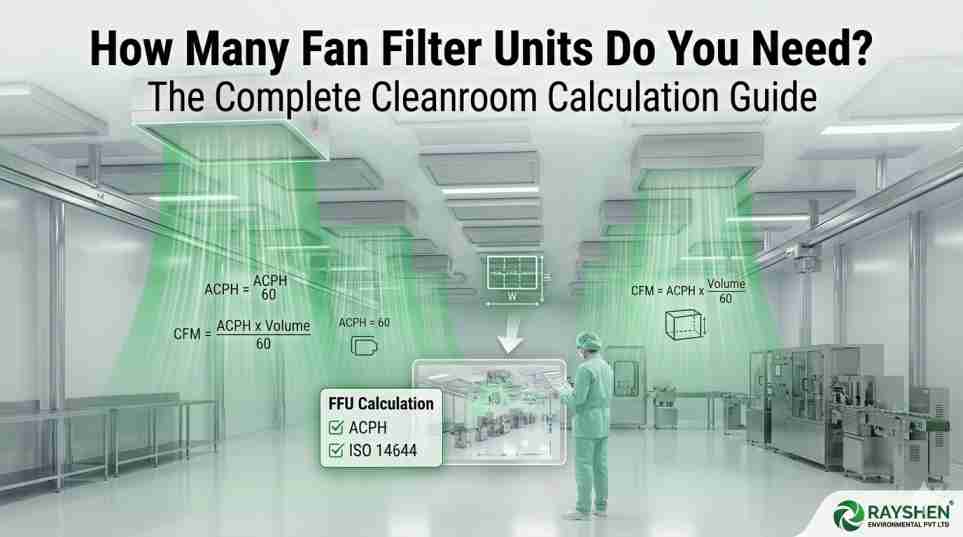
In any controlled environment — from a pharmaceutical aseptic suite to a semiconductor wafer fabrication facility — the Fan Filter Unit (FFU) is the most critical component of contamination control. It is the device that continuously delivers clean, filtered air to the working zone, maintaining the precise particle counts mandated by ISO 14644-1.
A Fan Filter Unit is a self-contained, ceiling-mounted module comprising a motorised fan, a pre-filter, and a terminal HEPA or ULPA filtration stage. Operating as part of an integrated cleanroom ceiling grid, each FFU draws recirculated or make-up air through its filter media and discharges it as a uniform, downward-flowing laminar airstream — the single most effective mechanism for diluting and removing airborne particulate contamination from the occupied zone below.
The industry-standard FFU 2x4 size (610 mm × 1,220 mm) has become the universal module because it aligns precisely with standard T-bar ceiling grids, enabling scalable coverage from 5% of ceiling area in an ISO 8 corridor to 100% in a critical ISO 5 Fan Filter Unit array over an aseptic filling line.
Yet despite its centrality to cleanroom performance, the Fan Filter Unit count calculation is routinely under-engineered — with designers defaulting to experience-based estimates rather than rigorous formula-driven methodology. This guide corrects that. Written for cleanroom contractors, HVAC consultants, pharmaceutical facility managers, and hospital administrators, it provides a step-by-step framework to calculate, specify, and optimise your Cleanroom Fan Filter Unit installation.
ISO 14644-1 Standards — The Regulatory Framework Behind Every FFU Decision
Before a single FFU is sized, the engineering team must establish the target cleanroom classification. ISO 14644-1: Classification of Air Cleanliness by Particle Concentration superseded the US Federal Standard 209E (Class 100 to Class 100,000) and defines nine cleanroom classes based on maximum permissible airborne particle concentrations at specified sizes.
| ISO Class | FED-STD-209E Equiv. | Max Particles ≥0.5 µm/m³ | Typical Application | Terminal Filter |
| ISO 5 | Class 100 | 3,520 | Aseptic filling, semiconductor litho | ULPA U15/U16 |
| ISO 6 | Class 1,000 | 35,200 | Pharma Grade B, medical devices | HEPA H14 |
| ISO 7 | Class 10,000 | 352,000 | Pharma Grade C, hospital OR | HEPA H13/H14 |
| ISO 8 | Class 100,000 | 3,520,000 | Pharma Grade D, general assembly | HEPA H13 |
The ISO class drives two engineering parameters that feed directly into the FFU count formula: the required Air Changes Per Hour (ACPH) and the minimum ceiling coverage percentage. Both vary dramatically across classes:
| ISO Class | Min ACPH | Design ACPH Range
| Min Ceilin60% – 100%g Coverage | Laminar Flow Req. |
| ISO 5 | 240 | 360 – 600+ | 60% – 100% | Yes — fully laminar |
| ISO 6 | 150 | 180 – 300 | 40% – 60% | Yes — predominantly laminar |
| ISO 7 | 60 | 90 – 180 | 15% – 25% | No — turbulent dilution |
| ISO 8 | 10 | 20 – 60 | 5% – 15% | No — turbulent dilution |
These ACPH values define the total volume of filtered air that must be supplied to the room every hour. From this volumetric requirement — combined with the airflow output of a single Cleanroom Fan Filter Unit — the minimum unit count follows directly.
The Step-by-Step FFU Count Calculation Formula
The core formula for determining Fan Filter Unit count is derived from fundamental ventilation engineering and expressed as follows:
| Number of FFUs | (Room Volume [m³] × ACPH) ÷ (FFU Airflow [m³/hr]) |
| Where: 1 CFM | 0.02832 m³/min = 1.699 m³/hr |
| Standard 2×4 FFU @ 1,000 CFM | 1,699 m³/hr per unit |
There are two critical refinements engineers must apply to this baseline formula:
• Use dirty-filter airflow, not clean-filter airflow. As HEPA filters load with particulate over their service life, Pressure Drop across the media increases from ~150 Pa (clean) to ~450 Pa (dirty), reducing fan output by 15–25%. Always size to the end-of-life CFM value to maintain ISO compliance throughout the filter interval.
• Apply a 10–15% contingency multiplier to account for FFU positioning constraints, ceiling obstructions, and future-proofing against process changes.
Worked Example 1 — ISO 7 Pharmaceutical Grade C Suite (10 m × 8 m × 3 m)
Room Volume = 10 m × 8 m × 3 m = 240 m³
Design ACPH = 120 (mid-range ISO 7)
Total air vol/hr = 240 × 120 = 28,800 m³/hr
FFU dirty airflow = 850 CFM × 1.699 = 1,444 m³/hr
Base FFU count = 28,800 ÷ 1,444 = 19.9 → 20 FFUs
With 12% contingency = 20 × 1.12 = 22.4 → 23 FFUs
Ceiling coverage = 23 × (0.61 × 1.22) ÷ (10×8) = 21.5% ✓ (ISO 7 target: 15–25%)
RESULT: 23 Fan Filter Units (2×4 size, HEPA H13, EC Motor)
Worked Example 2 — ISO 5 Aseptic Filling Suite (6 m × 5 m × 2.8 m)
Room Volume = 6 m × 5 m × 2.8 m = 84 m³
Design ACPH = 480 (ISO 5 aseptic filling)
Total air vol/hr = 84 × 480 = 40,320 m³/hr
FFU dirty airflow = 800 CFM × 1.699 = 1,359 m³/hr
Base FFU count = 40,320 ÷ 1,359 = 29.7 → 30 FFUs
With 10% contingency = 30 × 1.10 = 33 FFUs
Ceiling coverage = 33 × 0.744 ÷ 30 = 81.8% ✓ (ISO 5 target: 60–100%)
RESULT: 33 Fan Filter Units (2×4 size, ULPA U16, Stainless Steel FFU)
Key insight: The ISO 5 room of 84 m³ requires 33 FFUs while the ISO 7 room of 240 m³ — nearly 3× larger — needs only 23. ISO class, not room size, is the primary driver of FFU count.
Section 3: Factors That Modify the Baseline FFU Count
The formula above provides a regulatory minimum. In real-world facilities, three additional variables routinely require the baseline count to be increased by 10–40%.
3.1 — Process Heat Load
Every piece of process equipment — freeze-dryers, autoclave exhaust vents, filling machines, isolators — generates sensible heat that creates thermal buoyancy currents opposing the downward laminar airstream. Above 500 W/m² of floor area, these currents re-entrain settled particles from surfaces, increasing contamination risk. Engineering guidance:
• Increase design ACPH by 10–15% for every 500 W/m² of heat load above baseline
• Rooms with heat loads above 2 kW/m² should be modelled using Computational Fluid Dynamics (CFD) prior to finalising FFU count
• Locating FFUs directly above heat-generating equipment improves particle washout in that zone
3.2 — Occupancy Density
A resting human body generates approximately 100,000 particles per minute ≥ 0.5 µm. A moving, gowned operator in an ISO 5 environment generates 10–100× more during dynamic activities. EU GMP Annex 1 (2022 revision) mandates that maximum occupancy limits must be validated during Operational (OPL) classification. As a sizing rule:
• Add 2–3 FFUs per additional operator above the baseline design occupancy in ISO 5–6 rooms
• In ISO 7–8 rooms, increase ACPH by 5–8% per additional occupant
3.3 — Room Geometry and Obstruction
L-shaped rooms, rooms with large process equipment below ceiling level, and rooms with structural beams all create dead zones where particle counts may be elevated despite adequate ceiling-average ACPH. Mitigation strategies include:
• Distributing FFUs asymmetrically, biasing coverage toward high-occupancy and high-risk zones
• Avoiding FFU placement directly above large equipment that deflects the laminar airstream
• Maintaining a minimum 2.4 m vertical clearance between FFU face and work surface for effective particle washout
3.4 — Pressure Drop and Filter Loading
HEPA and ULPA filter Pressure Drop increases from approximately 150 Pa (clean) to 450 Pa (end-of-life), reducing fan output by up to 25%. Using variable-speed EC motor FFUs with a centralized FFU Control System enables automatic compensation — increasing fan speed as filter resistance rises to maintain target airflow. Without this feature, fixed-speed AC motor units will deliver progressively lower ACPH as filters load, potentially breaching ISO class limits before the scheduled replacement.
Section 4: Why Material Choice Matters — Stainless Steel FFU vs Aluminium
The mechanical housing of a Fan Filter Unit is not merely structural — it is a contamination control surface that must endure repeated chemical cleaning, elevated humidity, and in critical pharmaceutical environments, Vaporized Hydrogen Peroxide (VHP) bio-decontamination cycles.
| Property | Stainless Steel FFU (SS 304 / 316L)
| Aluminium FFU (Anodised) |
| Corrosion resistance | Excellent — withstands VHP, IPA, bleach
| Moderate — limited VHP tolerance |
| Surface finish | Electropolished Ra < 0.8 µm
| Anodized Ra 1.0–1.6 µm |
| Particle generation | Minimal — no flaking or oxidation
| Low-moderate — anodizing can spall |
| Structural weight | Heavier (factor into ceiling load)
| Lighter — easier installation |
| Capex | 30–50% premium over Aluminium | Lower initial cost |
| Best application | ISO 5–6, pharma Grade A/B, hospitals
| ISO 7–8, electronics, general assembly |
| Regulatory preference | EU GMP Annex 1, FDA 21 CFR, WHO GMP | Acceptable for non-sterile zones |
For any facility targeting EU GMP Annex 1, USFDA 21 CFR, or WHO GMP compliance, the Stainless Steel FFU is the specified standard — not a premium option. The electropolished interior eliminates the micro-crevices that harbour microbial bio-burden, and the non-reactive surface survives aggressive decontamination schedules without surface degradation that would compromise cleanability over time.
From a lifecycle cost perspective, the higher capex of SS units is typically recovered within 3–5 years through reduced maintenance, eliminated surface remediation costs, and avoidance of contamination events — each of which carries a regulatory and financial cost that dwarfs the initial hardware premium.
Energy Efficiency and Noise Control
AC Motor vs EC Motor: The Engineering and Economic Case
Traditional AC motor Fan Filter Units operate at a fixed synchronous speed, consuming 150–250 W continuously regardless of cleanroom demand. In a 100-FFU pharmaceutical facility, this equates to 15–25 kW of continuous electrical load — over 131,000–219,000 kWh annually.
By contrast, FFU with EC Motor (Electronically Commutated brushless DC motor) technology delivers step-change improvements across every operating metric:
• 35–60% reduction in energy consumption through variable-speed operation matched to real-time cleanroom conditions
• Soft-start capability eliminating inrush current peaks and extending motor bearing service life
• 0–10 V / PWM / Modbus / BACnet control interfaces enabling full integration into centralised FFU Control Systems and Building Management Systems (BMS)
• Lower operating temperature — EC motors run 20–30°C cooler than AC equivalents, reducing the facility cooling load contributed by motor waste heat
• Automatic pressure compensation — fan speed increases automatically as HEPA filter Pressure Drop rises with loading, maintaining target CFM and ACPH throughout the filter service interval
Energy Savings Comparison — 100 FFU Facility
AC Motor FFU: 100 units × 200 W × 8,760 hrs = 175,200 kWh/year
EC Motor FFU: 100 units × 82 W × 8,760 hrs = 71,832 kWh/year
Annual saving: 103,368 kWh ≈ ₹8,27,000 – ₹10,34,000/year (at ₹8–10/kWh)
5.2 — Low Noise FFU Design for Hospital and Laboratory Environments
Hospital operating theatres, research laboratories, and occupied pharmaceutical suites operate under strict acoustic requirements — typically NC-35 to NC-45 (approximately 40–50 dB[A]). A Low Noise FFU — rated below 45 dB(A) at 1 m at full airflow — is essential in these environments. Key acoustic design features:
• EC motor with aerodynamic backward-curved impeller blades reducing blade-pass frequency tonal noise
• Anti-vibration isolation mounts between motor assembly and FFU casing
• Acoustic attenuator section on upstream air inlet to reduce turbulence broadband noise
• Variable-speed operation — reducing fan speed from 100% to 70% reduces noise output by 8–12 dB(A) while still maintaining ISO class compliance in low-occupancy periods
5.3 — Centralised FFU Control Systems
Modern FFU Control Systems integrate every unit in the facility into a unified BMS network, enabling capabilities that fixed-speed AC systems cannot provide:
• Real-time ACPH monitoring with automatic fan speed adjustment triggered by particle counter or differential pressure sensor feedback
• Predictive filter maintenance alerts based on Pressure Drop trending — replacing calendar-based replacement with condition-based maintenance, typically extending filter service life by 15–25%
• Zone-based optimisation — boosting FFU speed in occupied or active process zones while idling units in unoccupied areas
• 21 CFR Part 11-compatible audit trail generation — automatically logging all speed changes, alarm events, and maintenance activities to support GMP documentation requirements
Conclusion: A Rigorous, Five-Step Framework for FFU Specification
Determining the correct number of Fan Filter Units for a cleanroom is a multi-variable engineering problem that demands systematic methodology, not rule-of-thumb estimation. The framework this guide has established can be summarised in five steps:
1. Establish ISO 14644-1 target class and corresponding ACPH requirement
2. Apply the FFU count formula using dirty-filter airflow values and a 10–15% contingency margin
3. Adjust upward for heat load, occupancy density, room geometry, and filter pressure drop trajectory
4. Specify Stainless Steel FFU for ISO 5–6 and all GMP-regulated environments; anodized aluminium for ISO 7–8 non-sterile zones
5. Specify FFU with EC Motor and a centralized FFU Control System to achieve energy efficiency, acoustic compliance, and BMS integration
Executed correctly, this specification process delivers a Cleanroom Fan Filter Unit installation that achieves ISO compliance from day one, maintains it through the filter service life, and minimises the lifecycle cost of cleanroom operation. Done incorrectly, it produces a facility that fails its first environmental monitoring survey — a cost measured not in hardware, but in regulatory time, remediation expense, and production downtime.
Partner with Rayshen — Leading FFU Manufacturer India
Custom Fan Filter Unit Solutions for Pharmaceutical, Semiconductor, Hospital & Research Facilities
Rayshen Cleanroom Solutions engineers and manufactures Fan Filter Units to the most demanding cleanroom specifications in India and across South Asia. Our full product range covers every application in this guide:
• Stainless Steel FFU — SS 304 / SS 316L, electropolished, VHP-compatible — for ISO 5–6 and all GMP environments
• FFU with EC Motor — 35–60% energy savings, variable speed, Modbus/BACnet ready — for smart cleanroom facilities
• Low Noise FFU — < 45 dB(A) at 1 m — for hospital operating theatres, laboratories, and occupied suites
• ISO 5 Fan Filter Unit — ULPA U15/U16 filtration, 100% ceiling coverage capability — for aseptic and semiconductor applications
• FFU Control System — Centralised BMS-integrated control panels with 21 CFR Part 11-compatible data logging
• Custom FFU 2x4 Size — Standard 610 × 1,220 mm and bespoke dimensions for non-standard ceiling grids
Get Your Free FFU Count Calculation
Share your room dimensions, ISO class target, and process details with our engineering team.
.png)
.png)