FFU Airflow and Coverage: How to Calculate the Right Number of Units for Any Cleanroom
11-05-2026
In the precision-driven world of cleanroom engineering, the Fan Filter Unit (FFU) is the engine of environmental control. It is the primary component responsible for air purification, pressurization, and the maintenance of laminar airflow. However, one of the most frequent and costly mistakes in facility design is a failure to accurately calculate airflow requirements.
Under-specifying the number of units results in "dead zones" and stagnant air, leading to catastrophic contamination failures and rejected product batches. Conversely, over-specifying leads to excessive energy consumption, turbulent airflow, and unnecessary capital expenditure.
Whether you are designing a high-end ISO 5 Fan Filter Unit layout for a pharmaceutical filling line or a larger electronics assembly area, calculating the correct coverage is a balance of fluid dynamics, regulatory standards, and equipment capability. This guide provides the comprehensive technical framework needed to determine exactly how many units your cleanroom requires.
1. The Mathematical Foundation: Air Changes Per Hour (ACH)
The first step in any cleanroom calculation is not looking at the hardware, but at the regulatory standard you must achieve. Air cleanliness is defined by the number of times the total volume of air in a room is filtered and replaced every hour. This is known as Air Changes Per Hour (ACH).
Understanding the ISO 14644-1 Requirements
Different cleanroom classifications require vastly different ACH rates. In 2026, the industry benchmarks for ACH are:
ISO 8 (Class 100,000): Typically requires 15 to 25 air changes per hour.
ISO 7 (Class 10,000): Jumps to 30 to 60 air changes per hour.
ISO 6 (Class 1,000): Requires 70 to 160 air changes per hour.
ISO 5 (Class 100): Requires a staggering 240 to 480 air changes per hour.
For an ISO 5 Fan Filter Unit installation, the air is essentially being replaced every 7 to 15 seconds. This high frequency is necessary to ensure that any particle generated by personnel or machinery is immediately swept away before it can settle on a sensitive surface.
2. The Step-by-Step FFU Calculation Formula
To move from a theoretical ISO class to a physical bill of materials, engineers use a specific three-step calculation. This ensures that the Cleanroom Fan Filter Unit count is backed by data.
Step A: Calculate Total Room Volume ($V$)
The volume is the total three-dimensional space that needs to be treated.
$$V = \text{Length} \times \text{Width} \times \text{Height (Ceiling Height)}$$
Step B: Determine Total Required Airflow in CFM ($Q$)
To find the total Cubic Feet per Minute (CFM) required, multiply the room volume by the target ACH and divide by 60 (to convert hours to minutes).
$$Q = \frac{V \times \text{ACH}}{60}$$
Step C: Calculate the Number of Units ($N$)
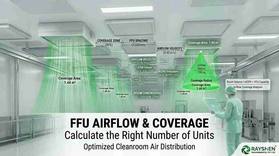
Divide the total required CFM by the rated output of a single unit. For a standard FFU 2x4 size, the typical rated airflow is approximately 650 to 800 CFM at a face velocity of 0.45 m/s.
$$N = \frac{Q}{\text{Output per FFU}}$$
Example: For a 1,000 sq. ft. ISO 7 cleanroom with a 10 ft. ceiling requiring 60 ACH, the total CFM needed is 10,000. If using an FFU that provides 700 CFM, you would need approximately 15 units.
3. Ceiling Coverage and Airflow Uniformity
While the math might tell you that 10 units provide enough air, the distribution of those units is what determines cleanroom success. This is where the concept of "Percentage of Ceiling Coverage" comes into play.
The Problem of Stagnant Zones
If you place all your FFU units in one corner, the other side of the room will have stagnant air, even if the total CFM is correct. To prevent this, engineers follow coverage guidelines based on ISO classes:
ISO 8: 5% to 15% coverage.
ISO 7: 15% to 25% coverage.
ISO 6: 25% to 40% coverage.
ISO 5: 60% to 80% coverage.
In an ISO 5 environment, the ceiling must be almost entirely comprised of FFU 2x4 size units. This creates "Laminar Flow," where the air moves in a unidirectional, downward path, effectively "washing" the room of contaminants.
4. Hardware Selection: Why Material and Noise Matter
Once the quantity is determined, the physical specifications of the Cleanroom Fan Filter Unit become the focus. The hardware must be able to withstand the calculated load without failing or creating an unworkable environment.
The Stainless Steel FFU Advantage
In pharmaceutical and biotech facilities, the housing of the unit must be as clean as the air it filters. A Stainless Steel FFU (SS304 or SS316L) is preferred because:
VHP Resistance: It can withstand Vaporized Hydrogen Peroxide sterilization without corroding.
Rigidity: Steel housings do not warp, ensuring that the HEPA filter seal remains airtight even under the high-pressure loads required for high ACH rates.
The Low Noise FFU Requirement
The cumulative noise of 50 or 100 fans running simultaneously can be deafening. OSHA regulations and worker productivity demand a Low Noise FFU. High-quality units utilize backward-curved impellers and acoustic insulation to keep noise levels between 48–54 dBA. When your calculation requires a high density of units, noise-reduction technology is not an option—it is a necessity.
5. Intelligent Control: The FFU Control System
A cleanroom is a dynamic environment. As HEPA filters age, they become clogged with particles, increasing resistance (static pressure). If your fans are set to a fixed speed, your airflow will slowly drop, eventually falling below the calculated ACH and failing ISO audits.
The Role of Centralized Control
An advanced FFU Control System allows for:
Automatic Speed Compensation: Using EC (Electronically Commutated) motors, the system senses the drop in airflow and automatically increases fan RPM to maintain the calculated CFM.
Group Zoning: You can decrease airflow in non-critical zones or during "night mode" to save energy.
Monitoring: Every unit is connected to a central PLC or BMS, providing real-time data on filter status and motor health.
6. Energy Efficiency and Heat Gain
Calculations must also account for the thermal impact of the units. Every Fan Filter Unit generates heat from its motor. If a room requires 100 units, the cumulative heat gain can be significant, potentially straining the cleanroom’s cooling system.
By selecting energy-efficient units with EC motors, you reduce the "Watts per CFM." This not only lowers the direct electricity cost of the fans but also reduces the load on the Chiller/HVAC system, leading to a much lower Total Cost of Ownership (TCO).
7. Procurement and Manufacturer Reliability
Finally, the accuracy of your airflow calculation depends on the manufacturer’s data being honest. When sourcing a Cleanroom Fan Filter Unit, always verify the "Fan Curves"—the graph showing how much air the unit moves at different static pressures.
As a leading FFU manufacturer in India, Rayshen ensures that every FFU 2x4 size unit is factory-tested and calibrated. Relying on an experienced partner means you get technical support for airflow mapping and smoke testing (visualization), ensuring that your calculated units perform as expected during the final validation.
Conclusion: Balancing Science and Hardware
Calculating the right number of units for a cleanroom is a rigorous process that blends volume, ISO standards, and ceiling geometry. From the robust Stainless Steel FFU to the intelligent FFU Control System, every component plays a role in maintaining the delicate balance of a sterile environment.
By following the ACH-to-CFM formula and respecting the ceiling coverage requirements of an ISO 5 Fan Filter Unit layout, facility managers can ensure long-term compliance and operational safety.
[Contact Rayshen’s Engineering Team for a Custom Airflow Mapping and FFU Quote]
Frequently Asked Questions (FAQs)
1. How do I calculate the number of FFUs needed for an ISO 5 cleanroom?
To achieve ISO 5 Fan Filter Unit compliance, you must first calculate the total room volume and multiply it by the required Air Changes Per Hour (ACH)—typically 240 to 480 for ISO 5. Divide the total required CFM by the rated output of your unit (usually 650–800 CFM for an FFU 2x4 size). Finally, ensure your layout provides 60% to 80% ceiling coverage to maintain laminar airflow.2. What is the difference between AC and EC motors in a Fan Filter Unit?
An EC (Electronically Commutated)motor is significantly more efficient than a standard AC motor. In a Cleanroom Fan Filter Unit, EC motors allow for variable speed control via an FFU Control System, enabling the unit to automatically increase its speed as the HEPA filter clogs. This ensures a constant airflow and saves up to 70% in energy costs compared to traditional AC models.
3. Why is a Stainless Steel FFU preferred for pharmaceutical cleanrooms?
A Stainless Steel FFU (specifically SS304 or SS316L) is the gold standard for pharma-grade environments because it is highly resistant to corrosion from sterilization agents like Vaporized Hydrogen Peroxide (VHP). Unlike aluminum or powder-coated steel, it does not shed particles or chip, ensuring the integrity of an ISO 5 Fan Filter Unit setup over a long lifecycle.
4. Can I control multiple Fan Filter Units from a single location?
Yes. Modern facilities utilize an advanced FFU Control System based on MODBUS or BACnet protocols. This allows a facility manager to monitor and adjust the speed of hundreds of units from a single touch-screen interface or a Building Management System (BMS), providing real-time failure alerts and filter status updates.
5. What noise level should I expect from a Low Noise FFU?
A high-performance Low Noise FFU is designed to operate between 48 and 54 dBA. Achieving low noise is critical in cleanrooms with high FFU density, as cumulative noise from dozens of units can otherwise exceed safety limits. Units from Rayshen use backward-curved impellers and acoustic baffling to ensure a quiet, productive workspace.
6. Is the FFU 2x4 size the most efficient for large cleanrooms?
The FFU 2x4 size is the industry favorite because it matches standard 1210x610mm ceiling grids, offering the best balance between filtration surface area and ease of installation. It provides higher CFM than a 2x2 unit while remaining manageable for a two-person maintenance team, making it the most cost-effective choice for large-scale modular cleanrooms.
.png)
.png)